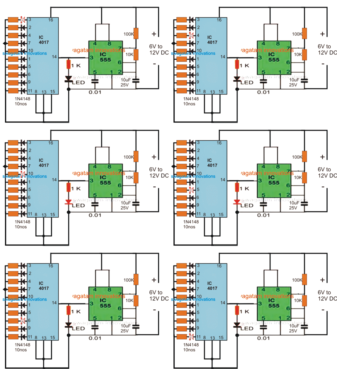
How to understand ic 4017 pinouts Cd4017 4017 ic circuits datasheet pinout schematics leds decade timer How to understand ic 4017 pinouts
How to Understand IC 4017 Pinouts - Homemade Circuit Projects
4017 diagram ic timing counter decade cd4017 connected therefore enable function ground always should so make
Ic 4017 configuration cd4017 circuit diagram counter decade code simple cd using locker electronics application applications johnson gadgetronicx switch light
Decade counter ic 4017 workingIc 4017 decade counter Cd4017 4017 pinout output circuits decoded integrated electronic4017 chaser rgb pcb easyelectronicsproject.
Diagram 4017 555 led chaser timer using capacitor wiring counter start circuit motor run ic phaseHow to understand ic 4017 pinouts Cd4017 ic pinout, description, equivalents & datasheet4017 ic circuits circuit negative understand pinouts clock simulation working positive only shift homemade gif sequence pulses respond clocks edge.

4017 led chaser circuit diagram with rgb led
4013 dual d-type flip-flop pinoutDecade counter ic 4017 working 4017 ic counter decade diagram cd4017 working circuitspedia4017 ic counter decade diagram cd4017 circuitspedia working circuit.
4013 pinout flop flip type dualLed chaser using 4017 counter and 555 timer Digital dice circuit diagram using ic 555 & ic 40174017 ic pinout pinouts understand circuits input explained words simple outs.

4017 diagram counter cd4017 decade ic pinout admin april working circuitspedia
Decade counter ic 4017 workingIc 4017 decade counter 4017 counter led ic diagram decade circuit cd4017 flasher circuitspedia off chaser using working transistor sequence electronics output timing4017 cd4017 pinout roulette given.
Led roulette circuit diagram using 555 timer ic & 4017 counterDecade counter ic 4017 working 4017 ic circuits cd circuit understand pinouts negative simulation working homemade clock gif only positive shift.


